
A. Willy
School of Mechanical & Aerospace Engineering
Nanyang Technological University
Singapore 639798
andre_willy@pmail.ntu.edu.sg
K. H. Low
School of Mechanical & Aerospace Engineering
Nanyang Technological University
Singapore 639798
mkhlow@ntu.edu.sg
Abstract – An environment-friendly propulsion system mimicking undulating fins of cuttlefish or stingray has been built. A nonconventional method was considered to model the flexibility of the fins of cuttlefish or stingray. A two-degree-of-freedom mechanism comprises several linkages was designed and constructed to mimic the actual flexible fin. The driving linkages are used to form a mechanical fin consisting of several fin segments, which are able to produce undulations, similar to those produced by the actual fins. Owing to the modularity of the design of the mechanical fin, we were able to construct various biomimetic robots of fish swimming by fin(s) undulations. Two variants are shown in this report: the first is a biomimetic robot of a of South American electric fish swimming by undulations of a long anal fin, and the second is a biomimetic robot of a cuttlefish swimming by undulations of its lateral fins. Some qualitative observations, obtained by experiments, predicted many factors affecting the thrust produced by the mechanical fins. Future work may include development other variants of biomimetic undulating fin robot and further development of the cuttlefish robot for autonomous deployment.
Keywords – biomimetics, modular robot, underwater robot, undulating fins, mechanism, flexible membrane, amplitude envelope, experiments.
I. INTRODUCTION
Recently researchers and scientists have been more vocal than in the past in
promoting an awareness to preserve environment. One of their main concerns is
the sustainability of underwater ecology, especially marine environment, which
is deteriorating due to extensive use of propellers and has recently gained
public and government attention.
Despite its versatility, propeller has created a certain concern for marine
life; it produces greater amount of marine debris, continued mortality of marine
creatures such as manatees as a result of propeller strikes, and disturbance
of shallow waters ecosystem.
Engineered counterpart or biomimetic [1] of natural locomotion could be the
solution the above addressed concern. Each species has its own unique and optimum
way of interacting with its environment, which then dictates the species’
body shape, body size, and the way it propels itself, as proposed by Darwinian
process of natural selection [2]. This leads to the development of an environment
friendly propulsion system, which mimics lateral undulating fins of cuttlefish
or pectoral fins of stingray.
In the field of underwater research, undulating-finned robot offers exceptional
advantage over propeller in preserving an undisturbed condition of its surroundings
for data acquisition. Autonomous underwater vehicles (AUV’s) are an interesting
area of application that could also greatly benefit from biomimetic mechanical
systems, as there is an increased demand for improved efficiency to allow for
longer missions to be undertaken. Military and defence are most important areas
where biomimetic finds its significant role in ensuring safe waters; the undulating
fin robot might be undetected when swim with a school of fish and therefore
may act as a spy.
II. BACKGROUND
A. Review on Fish Swimming Mode
Fish exhibit a variety of swimming movements which employ their fin(s) and/or
body to produce propulsive and maneuvering force. Breder [3] proposed two swimming
modes of fish based on the propulsive structure used: body and/or caudal fin
(BCF) locomotion and median and/or paired fin (MPF) locomotion.
(1) BCF Locomotion: Fish under BCF locomotion generate thrust by bending their
body into a backward-moving propulsive wave that extends to its caudal fin.
BCF Locomotion is further classified into five subcategories: anguilliform,
subcarangiform, carangiform, thunniform, ostraciiform.
In anguilliform mode, found in eel, lamprey and needlefish, the whole body participates
in large amplitude undulations that increase toward the tail and at least one
complete wavelength of the propulsive wave is present along the body [4]. The
inclusion of at least one wavelength of the propulsive wave along the body,
means that lateral forces are adequately cancelled out, minimizing any tendencies
for the body to yaw [5].
(2) MPF Locomotion: MPF locomotion is classified into several subcategories,
based on the fins used as the propulsive structure. Rajiform mode is found in
fish such as rays, skates, and mantas, whose swimming is very similar to the
flight of birds. Thrust is produced by large undulations along pectoral fins,
which span from the anterior to the posterior of the fish.
The amplitude envelope of the undulations increases from the anterior part to
the fin apex and decreases toward the posterior. Such amplitude envelope can
be explained from its triangular-shaped pectoral fins; they are narrower toward
anterior and posterior of the fish. The fins may also be flapped up and down
similar to the wings of birds.
In diodontiform mode propulsion is achieved by passing undulations down broad
pectoral fins. Up to two full wavelengths may be visible across the fins, while
undulations are often combined with oscillatory movements of the fin as a whole
[6].
In amiiform mode, fish swim by undulations of long-based dorsal fin, while the
body remains straight. Amiiform mode is found in gymnarchus niloticus. Its anal
and caudal fins are missing, while the dorsal fin extends along most of the
body length, tapering to a posterior point. Locomotor waves may pass in either
direction along the dorsal fin, and may show widely varying amplitude, particularly
during turning or braking [6]. Gymnotiform mode can be considered as the upside-down
equivalent of amiiform mode, since propulsion is obtained by undulations of
a long-based anal fin. In this mode, the fish do not have dorsal and caudal
fins. Gymnotiform can be found in gymnotus carapo. Labriform and tetraodontiform
are however not subjects of interest in our research because their fins are
oscillating, instead of undulating, to create momentum in water for propulsion.
Reader may visit [7]-[8] for further discussion on oscillatory fin movements.
The proposed research is intended to investigate which of the various swimming
modes – anguilliform, subcarangiform, rajiform, amiiform, and gymnotiform
– suits biomimetic underwater robot application using undulatory fins
as main thrust-generator. Empirical inference will be made based on results
obtained from underwater experiments with the robot.
B. Cuttlefish
Cuttlefish is a marine cephalopod of the order Sepioidea, related to the octopus
and squid and characterized by a thick, internal, calcified shell called the
cuttlebone [9]. Amazingly, this animal can regulate fluid to air ratio in its
cuttlebone, and therefore alter the level of buoyancy [10]. For defense, cuttlefish
has a fascinating capability to change its skin texture (camouflage) to fit
environment; ink is the last resort to blind its enemy and escape. There are
approximately 100 species of cuttlefish range between 2.5 and 90 centimeters
and have somewhat flattened bodies with a pair of narrow fins that extend along
the body.
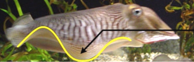
Fig. 2 Lateral fin of a cuttlefish fitted with a sinusoidal waveform.
The lateral fins of cuttlefish (Fig. 2) produce rhythmic undulatory waves,
which are used in locomotion and hovering. Although much of the thrust is given
by contracting its mantle during jet propulsion, the fins aid in producing thrust
at low swimming speeds, in rendering stability, and in supplying lift for hovering.
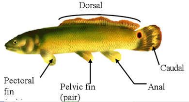
3 Morphology of Bowfin, a ray-finned fish swimming with long-based dorsal fin. This fish is classified under Amiiform swimming gait by Breder [3], [6].
Unlike ray-finned fish (Fig. 3) whose fins are supported by bones, the fins of cuttlefish lack rigid supportive elements; they instead contain three-dimensional array of musculature termed a ‘muscular hydrostat’. The muscle in the fin enables the cuttlefish to fully control undulations amplitude, wavelength, and speed of its fins accordingly depending on its activity; gentle, low amplitude, low frequency fin movements
are observed during hovering or when the animals rest on the substratum;
brief bursts of high amplitude and high frequency fin movements are observed
during rapid locomotion and maneuvering [11].
III. MECHANICAL FIN DESIGN
A. Design of Fin Rays
Fig. 3 shows an example of a ray-finned fish, a bowfin, with a long-based
dorsal fin. The fin consists of fin-rays and a flexible membrane connecting
them together. In median fins a set of muscles (usually six) for each fin-ray
provide the latter with two degrees-of-freedom movement capability, while
it has been suggested that certain fish can actively bend the rays of their
median fins [4], [6].
Kier and Thompson [11] Suggest that fins of cuttlefish are supported by three-dimensional
array of muscle; no fin ray is found in the fins of cuttlefish. Although the
designs of actuators, both linear and rotary, are not exhaustive, they are
however unable to model the complex musculature of the fins of the cuttlefish.
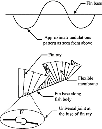
Fig. 4 Fin supported by rays. The base of each fin ray can be modelled by a universal joint (U) allowing two degrees of freedom movement for each fin ray [4], [6], [12].
Despite the complexity of the actual musculature, the fins of
cuttlefish exhibit much the same undulations as that displayed by the fins
of ray-finned fish with undulatory swimming mode. In order to simplify our
modeling, the fin of cuttlefish is divided into many segments such that the
fin looks similar to that of ray-finned fish. We may therefore conclude from
the mechanical point of view that the fins of cuttlefish can also be supported
by rigid structure such as fin rays as far as to perform undulatory movements.
Fig. 4 shows fin diagram of any fish, including that of cuttlefish, performing
undulations. Universal joint is (U) one possible joint that permits two degree
of freedom movements at the base of each fin ray.
At the present stage, mechanical modeling of undulating fins, which include
those of cuttlefish and ray-finned fish, is simplified to one degree of freedom
from originally two degrees of freedom at the base of each fin ray. A servomotor
serves as a muscle producing one degree of freedom at the base of each ray.
A crank is attached at each servomotor to function as a fin ray. In order
for the fin to exhibit undulations similar to that of any undulating fin,
each servomotor is programmed so that the crank attached to the servomotor
oscillates based on a sinusoidal function with a certain phase lead or lag
defined by ? (Fig.5). Ten servomotors are used to model one module of mechanical
fin.
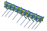
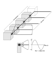
Fig. 5 (a) Ten servomotors are spaced equally. (b) Isometric
view of servomotors arrangement. Each servomotor serves as a muscle and a
crank a fin ray.
B. Design of Flexible Membrane
Flexible materials such as plastic sheet, cloth, and thin rubber sheet are
conventionally considered to model a membrane and connect all the cranks.
One main disadvantage of such materials when used as flexible membrane is
they assume any unpredictable shape which can disturb the water flow and movement
of the fin. Thin rubber sheet is in fact an ideal material which must be used
to model a flexible membrane. In this application, however, the rubber is
required to elongate up to 200% of its initial length, and extra power is
needed therefore in addition to the power required to push water.
Realizing the drawback of conventional materials, a mechanism was designed
and built to model any sinusoidal waveform discretely by a series of straight
lines – one straight line joins two points on a sinusoidal curve (Fig.
6).
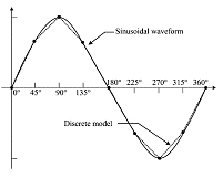
(a)
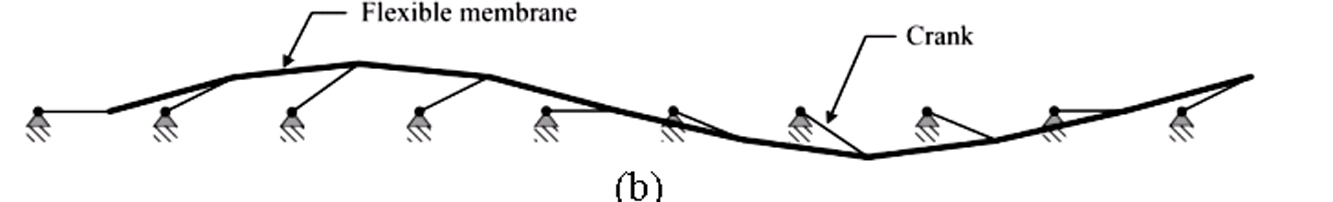
Fig. 6 (a) Discrete model of a sinusoidal waveform developed by a series of
straight lines joining two points every 45°. (b) Two cranks are connected
by a straight line.
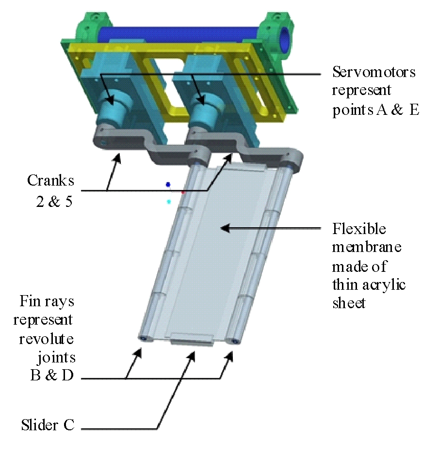
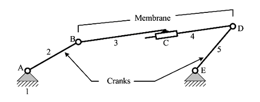
Fig. 7 (a) CAD picture of one fin segment. (b) Kinematic diagram of (a).
The mechanism will enable the flexible membrane to maintain a straight line between two cranks and at the same time extendible since the distance between two cranks changes as they oscillate. Fig. 7 shows the kinematic diagram of a linkage representing two cranks and a membrane. The linkage consists of five links and five lower pairs. Gruebler [12] states that degrees of freedom of a mechanism is
![]() , (1)
, (1)
where dof is the total degrees of freedom, n number of links
including the frame, l number of lower pairs, and h umber of higher pairs.
Kutzbach defines degrees of freedom as the number of actuators to be independently
controlled in a mechanism. Equation (1) correctly anticipates that the linkage
in Fig. 7 possesses two degrees of freedom since points A and E are each driven
by a servomotor.
Proper material selection is inevitable in the design of the flexible membrane.
Material density, strength, and water absorption capability are important
criteria for selection. The material is required to have a density near that
of water so that no or little work is done to lift and orientate the membrane
[13]. A polymer, acrylic, was therefore chosen for the flexible membrane since
its density is 1.2 times that of water.
IV. THEORY
An underwater robot was built based on undulatory swimming of cuttlefish and
stingray. The robot is propelled by a pair of undulating fins; undulations
of each fin are controlled by ten equally spaced servomotors to which are
connected cranks of the same length, as shown in Fig. 1. Each fin consists
of nine fin segments – one fin segment, shown as link BC in Fig. 8,
is controlled two servomotors. Each fin segment is connected to the adjacent
one by a revolute joint.
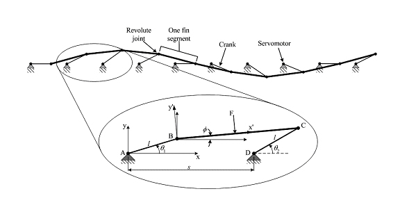
Fig. 8 Two-degree-of-freedom mechanisms constitute an undulating
fin.
The analysis of the fin will be simplified to one fin segment, which is controlled
by two servomotors A and D whose angular displacements with respect to x-axis
are specified by ??? and ??? as shown in Fig. 8. Bear in mind that the linkage
in Fig. 1 has two degrees of freedom and BC is a link whose length varies
according to the orientations of crank AB and DC.
Consider the enlarged fin segment in Fig. 8 moving forward parallel to x-axis
at constant speed V, and the two servomotors performing harmonic oscillations
according to the following functions:
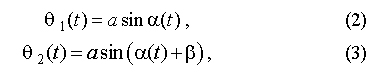
Anderson et al. [14] suggest that under these conditions, the fin segment is subject to time-varying force K(t). The servomotors have to provide torque inputs of Q1(t) and Q2(t). If m is the period of oscillation of the fin segment, let F be the time-averaged value of K(t), and P the average input power per cycle:
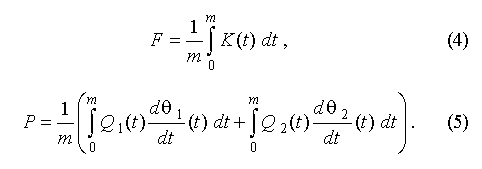
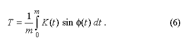
The time-average useful force along x- axis, Thrust T, is given by:
Collectively, for n number of segments, T assumes greater value which is theoretically nT; in this case any hydrodynamic interaction is ignored as propulsive waves propagate along the fins. The propulsive efficiency, ?, is defined to be the ratio of useful power over input power P, as
Despite common undulatory swimming technique, each of the species
has a unique way in making propulsive wave by using their body and/or fin(s)
– hereinafter called swimming gaits – depending on their body
stiffness, shape and length of fin(s), and many more factors.
The most well known example of a species with undulatory swimming gait is
eel; other examples include shark and needlefish, which are all anguilliform
swimmers. They undulate from one-third to almost all of their bodies, depending
on the speed, often with one or more complete waves present at a time. Lighthill
[15] proposes (8) to represent body undulations of a swimming eel shown in
Fig. 9:
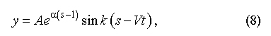
where A is the tail beat amplitude, ? is a parameter defining how fast the amplitude grows from head to tail, k defines how many number of waves present (equal to ???wave length), and V is the body wave propagation speed.
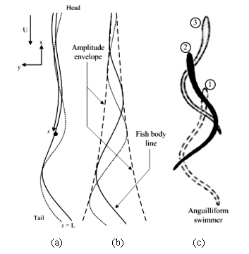
Fig. 9 (a) Coordinate systems for elongated body modeling. (b) Amplitude envelope defining the boundary of undulations. (c) Eel swimming from position 1 to position 3 with undulation amplitude growing from head to tail.
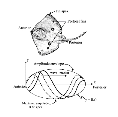
Fig. 10 Morphology of stingray and estimated amplitude envelope of its pectoral fins.
Here, we are interested in applying Lighthill’s proposal
of the swimming gait of eel – undulation amplitude grows from head to
tail – to the present mechanical system. Interested reader may refer
to [15] for a detailed discussion on elongated body theory.
A different yet interesting swimming gait is found in rajiform swimmer such
as stingray. Thrust is produced by large undulations along pectoral fins,
which span from the anterior to the posterior of the fish. The amplitude envelope
of the undulations increases from the anterior part to the fin apex and decreases
toward the posterior as shown in Fig. 10. Such amplitude envelope can be explained
from its triangular-shaped pectoral fins; they are narrower toward anterior
and posterior of the fish. The swimming of stingray is often likened to the
flight of birds due to the design of the fins that allows them to be flapped
up and down.
Cuttlefish, although not included by Breder’s classification, is also
observed using its fin for low speed swimming. Besides using water jet propulsion,
some wide-finned cuttlefish however swim like a rajiform swimmer i.e. by passing
large amplitude undulations along their fins and also flapping their fins
to for high-speed locomotion. The amplitude envelope of the fin undulations
of those cuttlefish is similar to that of rajiform swimmer as shown in Fig.
3. It is however observed that in smaller and narrow-finned cuttlefish, the
amplitude envelope is fairly constant along the fins, as shown in Fig. 11.
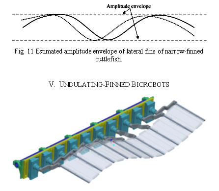
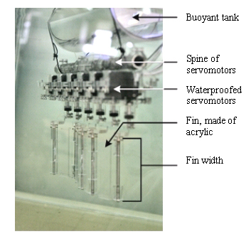
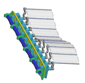
Fig. 12 One module of undulating fin consisting of ten equally
spaced servomotors attached to a lightweight structure, ten cranks representing
ten fin rays, and nine fin segments.
In order to investigate which of the suggested amplitude envelope provides
the maximum efficiency for undulating fin propulsion, one module of undulating
fin (Fig. 12) was designed and built. The fin can accommodate 10-cm peak-to
peak amplitude, various wave speeds, amplitude envelopes, and wavelengths.
The servomotors are programmable and can accept various time-dependent and
time-independent inputs that allow the fin to act as a propulsion system and
a control surface [16], respectively. Being modular, some of the fin segments
can be detached from the module, and hence changing the effective fin length.
Biorobot counterparts of various fish swimming with undulating fin(s) were
considered, such as bowfin, south american electric fish, knifefish, and cuttlefish,
to name a few.
A. Gymnotus Carapo Robot
Due to the nature of the mechanical system being modular, some experiments
was successfully conducted to mimic an underwater species, called gymnotus
carapo or south american electric fish which swims with a long-based anal
fin by constructing a biomimetic underwater robot shown in Fig. 13. Two experiments
were done: first experiment used 12 cm fin width, and the second one 20 cm.
Although no quantitative data was obtained from the experiment, it was however
found that the robot moves faster with wider fin. Wave amplitude and speed
were also found to be proportional to the thrust produced by the undulating
fin. At this point in time, no data has yet determined the effect of wavelength
on the propulsive thrust. Qualitative observations during the experiments
suggest that shorter wavelength is mandatory for low speed swimming as it
contributes significantly to the stability of the robot or in other words
small (undetected by eye) body oscillations. Therefore depending on the fin
length of the robot, it is necessary to have as many waves present along the
fin as possible in order to achieve fairly stable robot for cruising at low
speed.
Fig. 13 Gymnotus Carapo robot.
It must be noted however that the theory proposed earlier in this report is
unable to predict which envelope shape gives highest efficiency because of
neglected hydrodynamic interaction when the fin segments oscillate; the theory
only provides qualitative insights. From the experiments done on the first
prototype, biomimetic of gymnotus carapo, it can be established that thrust
T is:
![]()
where w is the fin width, A wave amplitude, V wave speed,
and ? defines wavelength of undulations.
B. Untethered Cuttlefish Robot
The encouraging results from the first experiment drove the research further
to building a second prototype mimicking a cuttlefish, a marine animal that
rhythmically undulates its fins for locomotion and maneuvring.
Previous researches in the area of undulating fin include the development
of a 1-m long by 1/3-m deep undulating fin device actuated by parallel bellows
which allow fin bending [17], and the development of a 53-cm long by 5-cm
deep rigid ribbon fin structure used by a black ghost knifefish [18]. Our
emphasis is to establish a research platform in a form of a robot consisting
of a pair of undulating fins with variable amplitude envelope, peak-to-peak
amplitude, wavelength, fin length, and speed.
Instead of modeling the fin muscle of the cuttlefish, its fins were designed
with a support structure similar to that of ray-finned fish. One fin length
was divided into nine segments driven by ten digital servomotors representing
the muscles at the base of fin rays. In order to achieve 10-cm peak-to peak
amplitude of undulation when actuators were positioned every 90° along
the wavelength, the length of each segment was determined to be 9 cm. The
total fin length is therefore 81 cm, with a fin width of 20 cm. One pair of
fins was fabricated and assembled together with other structural elements
to form a biomimetic cuttlefish robot.
The cuttlefish robot was built completely untethered by having
on board power supply and controller. Twenty servomotors (Futaba S3801) were
controlled by a customized control board comprising six microcontrollers (Basic
Stamp BS2SX), which were arranged and synchronized in multilevel communications
for efficient programming. The microcontrollers proved to be sufficient in
performing all the required calculations, which accommodate almost all experimental
variables such as amplitude envelope, peak-to-peak amplitude, speed, and wavelength,
in 15 ms.
VI. CONCLUSION AND FUTURE WORK
Although all the fin rays seem to oscillate independently, they are however
driven by the same sinusoidal function but at different phase lead or lag.
A mechanism can be developed to enable the fin rays to oscillate sinusoidally
at a certain phase lead or lag, and therefore reducing the number of actuators,
cost, and weight of prototype. In addition to actuators, it is interesting
to take note studies done by [19] which suggests the possibility of tissue
fibres in the fin of cuttlefish storing elastic energy during fin bending,
thus allowing the fin to function as a harmonic oscillator and thereby increasing
the efficiency of the fins during locomotion. More thorough study on cuttlefish
locomotion must be done in order to render proper and efficient control action
on the current robot.
Due to the nature of the fin being made of acrylic, a rigid material, and
independent control of each fin ray, the application of this fin is not limited
only to oscillating fins. Besides sinusoidal function with time-dependent
input, the robot microcontroller also accept other time-independent functions
which allow the fin of the robot to generate a particular curve, depending
on input function, which can be used as control surface while flying in water
[16]. All fish, including cuttlefish, squid and ray, use their fins as control
surface to maneuver when they have gained speed.
The future of biomimetic application relies on the advanced development of
actuators. Emerging biologically inspired materials such as Electro-active
Polymer (EAP) and shape-memory polymer (SMP) suggest avenues worth pursuing
which then may replace current motor-based actuators, such as servomotors.
EAP has a potential in modeling the fish muscles, including undulating fins
[20], [21].
Despite the absence of quantitative data from the initial experiments, the
results obtained from many observations in the experiments encourage and inspire
us to proceed further in investigating factors contributing to propulsive
thrust and efficiency of the undulating fins.
Future research works will develop other variants of biomimetic robots utilizing
the modular mechanical fin and investigate the meneuverability and control
aspect of a biomimetic robot with only one undulating fin. Future focus will
be on data acquisition from experiments, which will be used to analyze the
deployability – feasibility for deployment – of the cuttlefish
robot.
ACKNOWLEDGMENTS
The authors wish to thank Dr. F.M.J. Nickols for his valuable
feedback in the early stage of the development of the first prototype. He
also generously provided all waterproofed casings for the servomotors used
in the cuttlefish robot. We thank technicians of Computer Numerical Control
Laboratory for assistance in manufacturing components of the cuttlefish robot.
We also want to acknowledge the support from Professor Gerald Seet, the Director
of Robotics Research Center (RRC), and the technicians at the RRC on water
tank, electronic equipment, and other facilities.
REFERENCES
[1] S. Vogel, “Cat’s Paws and Catapults”, W.W Norton, New
York, 1998.
[2] F. E. Fish, “Limits of Nature and Advances of Technology: What Does
Biomimetics Have to Offer?”, in Proc. Of 1st Int. Sym. on Aqua Bio-Mechanisms,
N. Kato and Y. Suzuki, Eds., Tokai University Pacific Center, 3-12, Hawaii,
2000.
[3] C. M. Breder, “The Locomotion of Fishes“, Zoologica, vol.
4, 159-297, 1926.
[4] M. Sfakiotakis, D. M. Lane, and J. B. C. Davies, “Review of Fish
Swimming Modes for Aquatic Locomotion”, IEEE J. Oceanic Eng., vol. 24,
237-252, 1999.
[5] C. C. Lindsey, ”Form, Function and Locomotory Habits in Fish”,
in Fish Physiology Vol. VII Locomotion, W. S. Hoar and D. J. Randall, Eds.
New York: Academic, 1-100, 1978.
[6] Fish swimming gaits,
http://www.ece.eps.hw.ac.uk/Research/oceans/projects/flaps/mpfmodes.htm, Jan
2005.
[7] J. A. Walker and M. W. Westneat, “Performance Limits of Labriform
Propulsion and Correlates with Fin Shape and Motion”, J. Exp. Biol.,
vol. 205, 177-187, 2002.
[8] J. A. Walker and M. W. Westneat, “Kinematics, Dynamics, and Energetics
of Rowing and Flapping Propulsion in Fishes”, Integr. Comp. Biol., vol.
42, 1032-1043, 2002.
[9] Encyclopedia, cuttlefish, www.britannica.com, Jan 2005.
[10] Amazing cuttlefish, http://www.windspeed.net.au/~jenny/cuttlefish/anatomy.html,
Jan 2005.
[11] W. M. Kier and J. T. Thompson, “Muscle Arrangement, Function and
Specialization in Recent Coleoids”, in Proc. Coleoid Caphalopods through
Time, vol. 3, 141-162, Berlin, Sept. 2002.
[12] C. E. Wilson and J. P. Sadler, “Kinematics and Dynamics of Machinery”,
2nd ed., 1-20, New York: Harper Collins, 1993.
[13] P. W. Webb, “Maneuverability – General Issues”, IEEE
J. Oceanic Eng., vol. 29, 547-555, 2004.
[14] J. M. Anderson, K. Streitlien, D. S. Barrett, and M. S. Triantafyllou,
“Oscillating Foils of High Propulsive Efficiency”, J. Fluid Mech.
vol. 360, 41-72, 1998.
[15] M. J. Lighthill, “Large-amplitude Elongated-body Theory of Fish
Locomotion”, Proc. R. Soc. Lond. A vol. 179, 125-138, 1971.
[16] F. E. Fish et al., “Conceptual Design for the Construction of a
Biorobotic AUV Based on Biological Hydrodynamics”, in Proc. Of the 13th
int. Sym. of Unmanned Untethered Submersible Technology, New Hampshire, 2003.
[17] M. Sfakiotakis, D. M. Lane, and B. C. Davies, “An Experimental
Undulating-fin Device using the Parallel Bellows Actuator”, in IEEE
Int. Conf. Robotics Automation, 2356-2360, Seoul, 2001.
[18] M. A. MacIver, E. Fontaine, and J. W. Burdick, “Designing Future
Underwater Vehicles: Principles and Mechanism of a Weakly Electric Fish”,
IEEE J. Oceanic Eng., vol. 29, 651-659, 2004.
[19] S. Johnsen and W. M. Kier, “Intramuscular Crossed Connective Tissue
Fibers: Skeletal Support in the Lateral Fins of Squid and Cuttlefish (Mollusca:
Caphalopoda)”, J. Zool. Lond. vol. 231, 311-338, 1993.
[20] J. W. Paquette and K. J. Kim, “Ionomeric Electroactive Polymer
Artificial Muscle for Naval Applications”, IEEE J. Oceanic Eng., vol.
29, 729-737, 2004.
[21] A. Punning, M. Anton, M. Kruusmaa, and A. Aabloo, "A Biologically
Inspired Ray-like Underwater Robot with Electroactive Polymer Pectoral Fins",
in Proc. of the Int. IEEE Conf. Mechatronics and Robotics 2004 (MechRob'04),
vol. 2, 241 – 245, Aachen, 2004.